*
The RoHS icon on this product indicates that the PCBs, components, solder, and chemicals are all lead-free and RoHS compliant. Additionally, this product is produced using a lead-free process. Unfortunately, we are currently unable to provide documentation confirming that this product is RoHS compliant.
Resources:
*
If your browser cannot display the PDF file properly, please save it to your computer and open it with a PDF reader.
Package Includes:
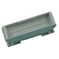
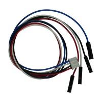
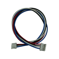
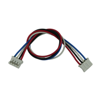
 This package does not include Din-Rail PCB holders and cables.
Notes:
This package does not include Din-Rail PCB holders and cables.
Notes:
- This package does not include Din-Rail PCB holders and cables.
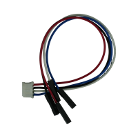
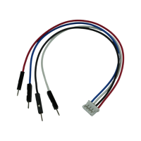
- This board uses 4-pin connectors for I2C bus.
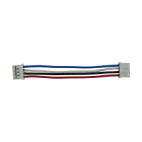
- Side by side linking of this products uses 2.5 inch (6 cm) long of wires.
Features:
- 4–20 mA Analog Outputs
- Supports up to two boards on a single I2C bus (this model)
- Supports up to eight boards on a single I2C bus (using multiple models)
- Built-in MCP4725A3 12-bit Digital-to-Analog Converter
- I2C Bus Operating Voltage: 3–5 V
- Requires 9–36 V power supply for analog output
- On-board I2C pull-up resistors included
- Compatible with most microcontrollers
- Reverse polarity protection for power supply
- Designed for DIN-rail PCB mounting
- PCB size: 72.00x20.00 mm
The I2C-AO112DI3V2 is an updated version of the original I2C-AO112DI3. The main circuit design remains unchanged; only the PCB has been redesigned, the LED has been removed to reduce current consumption, and the jumpers have been replaced with SMD types. Therefore, this version can be used as a direct replacement for the original version.
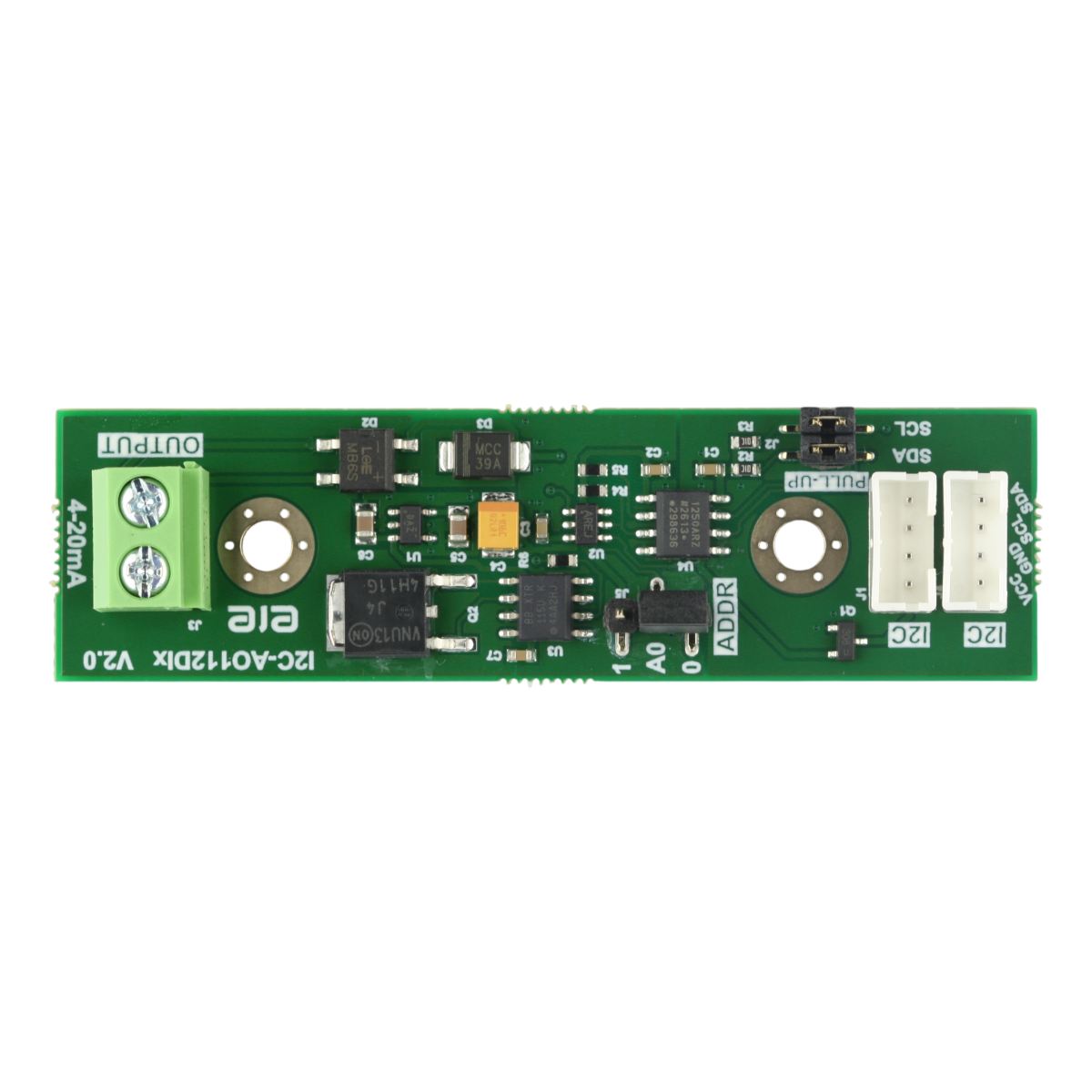
The I2C-AO112DI3V2 is a digital-to-analog output board. It is mountable on a DIN-rail PCB holder. It is designed for a 2-wire 4-20mA current loop transmitter, with the 4-20mA analog output controlled via the I2C bus. The board features a 12-bit digital-to-analog converter and includes an isolation chip that separates the I2C signals on the board from the I2C bus signals. This ensures that analog signals remain unaffected when multiple boards are connected to the same bus.
Additionally, the board is equipped with a surge protector, safeguarding it against transient voltage events. The I2C bus operates at a working voltage of 3-5V, while the power supply voltage for the 4-20mA analog output ranges from 9-36V. Built-in polarity protection circuits prevent damage caused by incorrect connections.
Up to two boards can be connected to the same I2C bus. However, it is possible to connect up to eight boards on the same bus by using two of each model: I2C-AO112DI0(V2), I2C-AO112DI1(V2), I2C-AO112DI2(V2), and I2C-AO112DI3(V2) -as each has a unique address.
This board incorporates a galvanic isolation IC to electrically isolate the I2C bus interface from the analog output stage. As a result, an external 9–36 V supply is required on the analog side to power the output circuitry when interfacing with a microcontroller.
To prevent damage to the board, do not plug or unplug I2C cables while the power supply is on. Always turn off the power supply before plugging or unplugging I2C cables on the board.